- 您现在的位置:买卖IC网 > Sheet目录1917 > DSPIC30F4011-30I/ML (Microchip Technology)IC DSPIC MCU/DSP 48K 44QFN
dsPIC30F4011/4012
DS70135G-page 160
2010 Microchip Technology Inc.
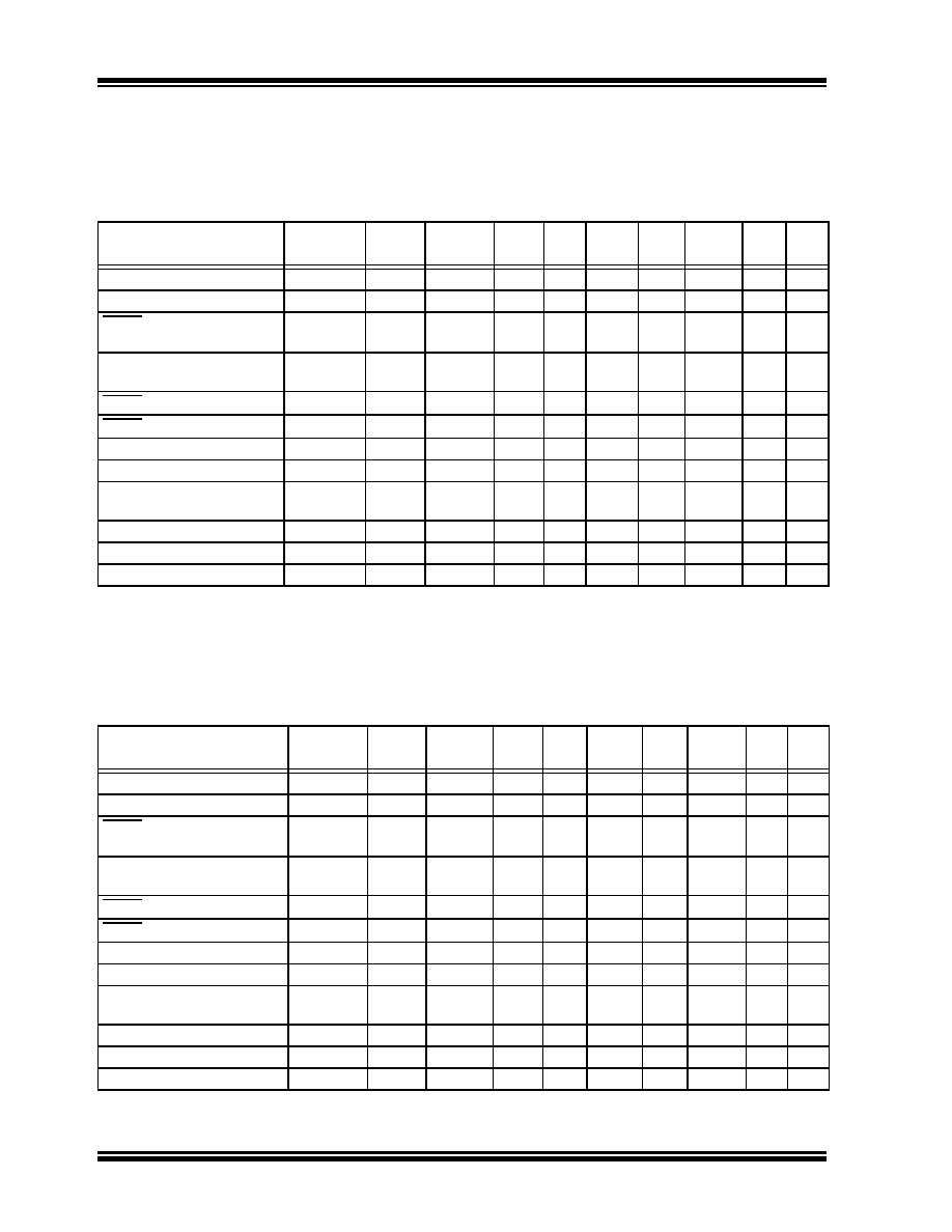
Table 21-5 lists the Reset conditions for the RCON
Register. Since the control bits within the RCON regis-
ter are R/W, the information in the table implies that all
the bits are negated prior to the action specified in the
condition column.
TABLE 21-5:
INITIALIZATION CONDITION FOR RCON REGISTER, CASE 1
lists
a
second
example
of
the
bit
conditions for the RCON register. In this case, it is not
assumed that the user has set/cleared specific bits
prior to action specified in the condition column.
TABLE 21-6:
INITIALIZATION CONDITION FOR RCON REGISTER, CASE 2
Condition
Program
Counter
TRAPR IOPUWR EXTR SWR WDTO IDLE
SLEEP POR BOR
Power-on Reset
0x000000
00
0
1
Brown-out Reset
0x000000
00
0
1
MCLR Reset during normal
operation
0x000000
00
1
0
Software Reset during
normal operation
0x000000
00
0
1
0
MCLR Reset during Sleep
0x000000
00
1
0
1
0
MCLR Reset during Idle
0x000000
00
1
0
1
0
WDT Time-out Reset
0x000000
00
0
1
0
WDT Wake-up
PC + 2
00
0
1
0
1
0
Interrupt Wake-up from
Sleep
PC + 2(1)
00
0
1
0
Clock Failure Trap
0x000004
00
0
Trap Reset
0x000000
10
0
Illegal Operation Trap
0x000000
01
0
Note 1:
When the wake-up is due to an enabled interrupt, the PC is loaded with the corresponding interrupt vector.
Condition
Program
Counter
TRAPR IOPUWR EXTR SWR WDTO
IDLE
SLEEP POR BOR
Power-on Reset
0x000000
00
0
1
Brown-out Reset
0x000000
uu
u
0
1
MCLR Reset during normal
operation
0x000000
uu
1
0
u
Software Reset during
normal operation
0x000000
uu
0
1
0
u
MCLR Reset during Sleep
0x000000
uu
1
u
0
1
u
MCLR Reset during Idle
0x000000
uu
1
u
0
1
0
u
WDT Time-out Reset
0x000000
uu
0
1
0
u
WDT Wake-up
PC + 2
uu
u
1
u
1
u
Interrupt Wake-up from
Sleep
PC + 2(1)
uu
u
1
u
Clock Failure Trap
0x000004
uu
u
Trap Reset
0x000000
1u
u
Illegal Operation Reset
0x000000
u1
u
Legend: u = unchanged
Note 1:
When the wake-up is due to an enabled interrupt, the PC is loaded with the corresponding interrupt vector.
发布紧急采购,3分钟左右您将得到回复。
相关PDF资料
DSPIC30F4013-30I/ML
IC DSPIC MCU/DSP 48K 44QFN
DSPIC30F5013-30I/PT
IC DSPIC MCU/DSP 66K 80TQFP
DSPIC30F5015-30I/PT
IC DSPIC MCU/DSP 66K 64TQFP
DSPIC30F6010-20E/PF
IC DSPIC MCU/DSP 144K 80TQFP
DSPIC30F6010A-30I/PF
IC DSPIC MCU/DSP 144K 80TQFP
DSPIC30F6013A-30I/PF
IC DSPIC MCU/DSP 132K 80TQFP
DSPIC30F6014-30I/PF
IC DSPIC MCU/DSP 144K 80TQFP
DSPIC33EP512MU814-I/PL
IC DSC 16BIT 512KB 144LQFP
相关代理商/技术参数
DSPIC30F4011-30I/P
功能描述:数字信号处理器和控制器 - DSP, DSC 16bit Signal Cntrlr RoHS:否 制造商:Microchip Technology 核心:dsPIC 数据总线宽度:16 bit 程序存储器大小:16 KB 数据 RAM 大小:2 KB 最大时钟频率:40 MHz 可编程输入/输出端数量:35 定时器数量:3 设备每秒兆指令数:50 MIPs 工作电源电压:3.3 V 最大工作温度:+ 85 C 封装 / 箱体:TQFP-44 安装风格:SMD/SMT
DSPIC30F4011-30I/PT
功能描述:数字信号处理器和控制器 - DSP, DSC 16 Bit MCU/DSP 30M 48KB FL RoHS:否 制造商:Microchip Technology 核心:dsPIC 数据总线宽度:16 bit 程序存储器大小:16 KB 数据 RAM 大小:2 KB 最大时钟频率:40 MHz 可编程输入/输出端数量:35 定时器数量:3 设备每秒兆指令数:50 MIPs 工作电源电压:3.3 V 最大工作温度:+ 85 C 封装 / 箱体:TQFP-44 安装风格:SMD/SMT
DSPIC30F4011T-20E/ML
功能描述:数字信号处理器和控制器 - DSP, DSC 16 Bit MCU/DSP 44LD 20M 48KB FL RoHS:否 制造商:Microchip Technology 核心:dsPIC 数据总线宽度:16 bit 程序存储器大小:16 KB 数据 RAM 大小:2 KB 最大时钟频率:40 MHz 可编程输入/输出端数量:35 定时器数量:3 设备每秒兆指令数:50 MIPs 工作电源电压:3.3 V 最大工作温度:+ 85 C 封装 / 箱体:TQFP-44 安装风格:SMD/SMT
DSPIC30F4011T-20E/PT
功能描述:数字信号处理器和控制器 - DSP, DSC 16 Bit MCU/DSP 20M 48KB FL RoHS:否 制造商:Microchip Technology 核心:dsPIC 数据总线宽度:16 bit 程序存储器大小:16 KB 数据 RAM 大小:2 KB 最大时钟频率:40 MHz 可编程输入/输出端数量:35 定时器数量:3 设备每秒兆指令数:50 MIPs 工作电源电压:3.3 V 最大工作温度:+ 85 C 封装 / 箱体:TQFP-44 安装风格:SMD/SMT
DSPIC30F4011T-20I/ML
功能描述:数字信号处理器和控制器 - DSP, DSC DIG SIG CONTR RoHS:否 制造商:Microchip Technology 核心:dsPIC 数据总线宽度:16 bit 程序存储器大小:16 KB 数据 RAM 大小:2 KB 最大时钟频率:40 MHz 可编程输入/输出端数量:35 定时器数量:3 设备每秒兆指令数:50 MIPs 工作电源电压:3.3 V 最大工作温度:+ 85 C 封装 / 箱体:TQFP-44 安装风格:SMD/SMT
DSPIC30F4011T-20I/PT
功能描述:数字信号处理器和控制器 - DSP, DSC 16 Bit MCU/DSP 20M 48KB FL RoHS:否 制造商:Microchip Technology 核心:dsPIC 数据总线宽度:16 bit 程序存储器大小:16 KB 数据 RAM 大小:2 KB 最大时钟频率:40 MHz 可编程输入/输出端数量:35 定时器数量:3 设备每秒兆指令数:50 MIPs 工作电源电压:3.3 V 最大工作温度:+ 85 C 封装 / 箱体:TQFP-44 安装风格:SMD/SMT
DSPIC30F4011T-30I/ML
功能描述:数字信号处理器和控制器 - DSP, DSC 16 Bit MCU/DSP 44LD 30M 48KB FL RoHS:否 制造商:Microchip Technology 核心:dsPIC 数据总线宽度:16 bit 程序存储器大小:16 KB 数据 RAM 大小:2 KB 最大时钟频率:40 MHz 可编程输入/输出端数量:35 定时器数量:3 设备每秒兆指令数:50 MIPs 工作电源电压:3.3 V 最大工作温度:+ 85 C 封装 / 箱体:TQFP-44 安装风格:SMD/SMT
DSPIC30F4011T-30I/PT
功能描述:数字信号处理器和控制器 - DSP, DSC 16 Bit MCU/DSP 30M 48KB FL RoHS:否 制造商:Microchip Technology 核心:dsPIC 数据总线宽度:16 bit 程序存储器大小:16 KB 数据 RAM 大小:2 KB 最大时钟频率:40 MHz 可编程输入/输出端数量:35 定时器数量:3 设备每秒兆指令数:50 MIPs 工作电源电压:3.3 V 最大工作温度:+ 85 C 封装 / 箱体:TQFP-44 安装风格:SMD/SMT